|
<< Click to Display Table of Contents >> Quick Start - Manual Project |
  
|
|
<< Click to Display Table of Contents >> Quick Start - Manual Project |
|
If you have no instrument connected clicking on New Manual Project will display the Input Required box

Enter a name for the project. SpecView will create a sub-folder with this name in the SpecView folder (which is normally C:\SV3\). The name you enter should follow the Windows file naming rules and should not be too long.
Remember this name. This folder will be where all log files and project files will be stored. Log Reports will also be stored here unless another folder is specified.
When a name has been entered click OK and this will immediately go into Edit Mode displaying a blank Graphical Display Window (GDW) grid.
Click the Variables List tool![]() on the Toolbar to display the Variables List. At this stage the only item listed will be SpecView.
on the Toolbar to display the Variables List. At this stage the only item listed will be SpecView.
Note: When using the Toolbar, move the pointer over a tool and the Tool Tip will say what it does.
Click the Templates tool ![]() on the Toolbar to display the Templates List, which will list the pre-defined instrument types:
on the Toolbar to display the Templates List, which will list the pre-defined instrument types:

Scroll down the list of available instruments to find the name of the instrument that is intended to be connected.
Click the ![]() symbol beside the instrument to display the specific instrument types. Select the appropriate one, then click Create Inst.
symbol beside the instrument to display the specific instrument types. Select the appropriate one, then click Create Inst.

Choose the COM Port from the list (for example COM1) and enter the Slave Address for the instrument together with the address Offset if needed and the number of Decimal Places that the values will need to show.
(To add instruments at COM ports greater than COM9 see setting MaxPorts)
Extra: This is only used by instruments like the Honeywell HC900 to access the the SPP block's Profile Descriptor Fields.
For help click the Help for Address or Instrument button.
For more information on Modbus addressing: Modbus instrument addressing
The instrument can be added to a group which allows a number of instruments that are being used for a specific purpose to be kept together in a logical way.
For example, a furnace, warehouse, etc.
Enter the Baud Rate and Parity appropriate for the instrument and click OK.
Please consult the instrument manufacturer's manual for more information.
Note: To test if the COM port that your instrument(s) are connected to is functioning correctly.
The instrument has now been defined within SpecView and will be listed in the Variables List.
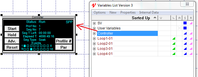
If the instrument has a large number of parameters, such as a multi-loop controller, then the parameters will be divided into a number of 'logical instruments' called Instrument Views.
For example, an 8-loop controller could have an Instrument View containing the parameters for the controller itself in addition to 8 Instrument Views containing the parameters for each of the loops.
The instrument View can itself be dragged out onto the GDW:
Parameters can be dragged out onto the GDW individually:
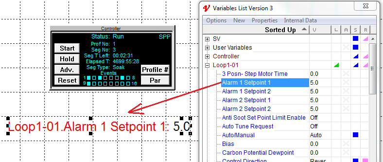
Or a number of parameters can be multi-selected and dragged out.
If using multi-select then the parameters will have additional 'handles' around them, which can be used to spread them out.
This is now configured as if the instrument was already connected and you had clicked the Test Comms for New Project button to automatically detect the instrument. Therefore you can now skip the next section, and go straight to Edit Mode, starting with Add a variable to the GDW