|
<< Click to Display Table of Contents >> Setting up SpecView Modbus Server |
  
|
|
<< Click to Display Table of Contents >> Setting up SpecView Modbus Server |
|
In the real world, instruments act like Modbus servers and SCADA software like SpecView act like Modbus clients.
Modbus clients request data and Modbus servers provide data.
Also, Modbus clients are able to send values to Modbus servers.
Traditionally, SpecView acts as a Modbus client.
It requests data from instrumentation, for example requesting the Process Value from a controller.
Also, SpecView can write values to instruments, for example altering the Set Point in a controller.
As of SpecView 3.1.275, SpecView can now act as a Modbus server as well.
SpecView can simultaneously be a Modbus client and Modbus server.
This will be beneficial to users who want to test their SpecView Projects without requiring physical hardware.
SpecView can simulate registers, coils, input values, alarms, and changing process data so that communication behavior can be verified in a controlled environment.
Enabling SpecView's Modbus Server
Using Generic Modbus to Read and Write Values (Preferred method)
Advanced example: Reading and Writing Values from Multiple SpecView Instances on the Network
Using Preferences to Write and Read Values
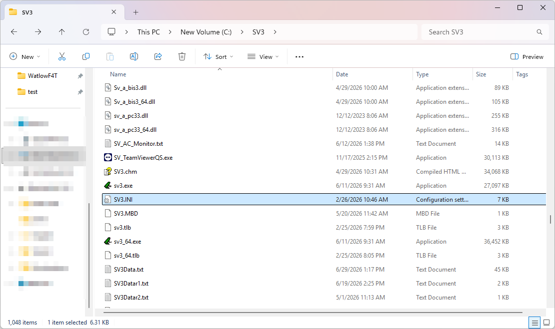
| 1. | Open the SV3 folder. By default, it is in the C drive (Local disk). If SpecView was installed to another drive, then the folder will be found in that drive. For more information contact the IT department or the SpecView representative that set up SpecView. |
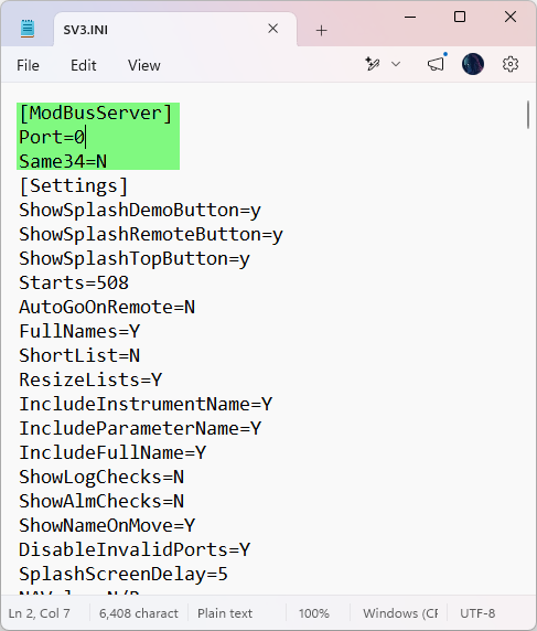
| 2. | Open the SV3.INI file.The file can be opened in a text editor such as Notepad. |
| 3. | At the top of the file enter the following: |
[ModBusServer]
Port=502
Same34=N
[ModbusServer] is a section header.
Port defines the port number on which the Modbus server will communicate through. The default port number for Modbus is 502. Users can select another available port if it is available.
Same34 means that a FC6 write writes to both FC3 (4X) and FC4 (3X) registers at the same time.
The Modbus server responds to Slave addresses 1 thru 255 and to FC1, FC2, FC3,FC4,FC6,FC10. All input and holding registers have a range of 0-65535.
The values are persistent. So, they will not be reset if SpecView is restarted.
4. Save the SV3.INI file.

Using Generic Modbus to Read and Write Values
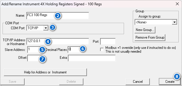
| • | In Edit Mode, from the New Instrument’s List, expand the Generic Modbus section by clicking on the “+” beside the section title and then select the appropriate instrument. |
| o | For Function Code 3, select 4X registers. |
| o | For Function Code 4, select 3X registers. |
| o | For a range of values from 0 to 65535, select unsigned registers. |
| o | For a range of values from -32768 to 32767, select signed registers. |

| • | Enter an appropriate name. |
| • | Select TCP/IP from the COM Port drop down menu. |
| • | Enter 127.0.0.1 for the IP Address. |
| • | Enter the correct Slave Address. |
| o | For example, values were previously entered into the server at Slave Address 1. So, here the Slave Address field would contain the value 1. |
| 6. | Enter the desired number of decimal places in the Decimal Places field. |
| 7. | Enter the correct Offset amount. Leaving the field blank will use the default value of 0. |
| 8. | Click on Create. |
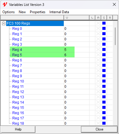
| 9. | In the Variables List, under the instrument name, the values will appear in the appropriate registers. |
| o | Open the Variables List by clicking on the Red V button in the Toolbar. |
| o | Expand the instrument in the Variables List by clicking on the “+” beside the instrument name. |
| o | In the current examples, the values 5 and 6 were set in registers 4 and 5 respectively. |
Advanced example: Reading and Writing Values from Multiple SpecView Instances on the Network
It is possible using SpecView’s Modbus server to read and write values from one instance of SpecView to another instance of SpecView on a different PC but on the same network.
So, for example, a user could set up a copy of SpecView on a PC in the Supervisor’s office that can seamlessly display the data being recorded from multiple copies of SpecView on the factory floor.
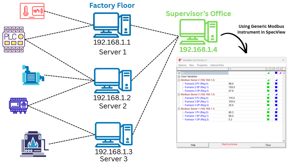
Follow the instructions below
| • | Set up the Modbus server as explained in the sections above. |
| • | Set up the Generic Modbus instruments as mentioned in the previous section. |
| • | Copy the values of the desired parameters into the Generic Modbus instrument. |
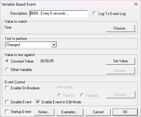
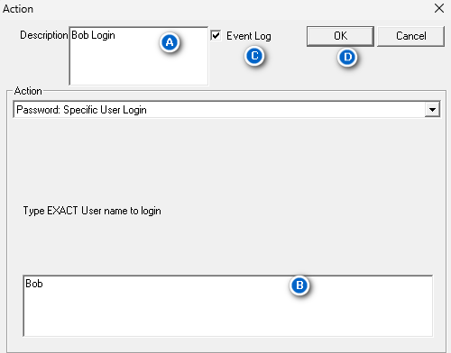
| o | This can be done in a given frequency or based on some other event using Strategy Controller. For more information, please read through the Strategy Controller section of SpecView’s help. |

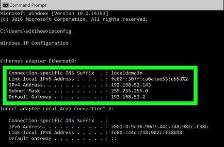
| • | Acquire the IP Address of the PC. |
| o | Using the command “IPCONFIG” in a Command Prompt terminal should provide the IP Address in the IPV4 field. |
| o | If the PC is on multiple networks, ensure that the correct IP Address is used for the next step. |
| o | Contact the IT department or the network administrator for further assistance, if it is required. |
Setting up to read values from a different PC
| • | Set up Generic Modbus as mentioned in the previous section with the following exception. |
| o | The IP Address of the instrument will be the IP Address of the PC that the Modbus server was set up on in Step 1. |
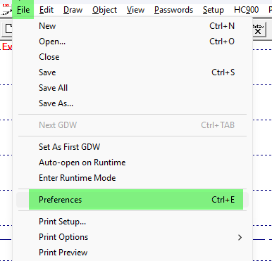
| 1. | In any SpecView project, open Preferences and navigate to the Debug tab. File > Preferences > Debug. |

| 2. | To see what data has been sent into the Server, use a RepCode value of 3 without any RepCode2. |
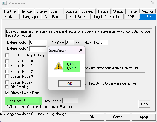
So, Slave Address 1, Function Code 3 (4X), in register 4 is the value 5; 1,3,4,5.
In register 5 is the value 6; 1,3,5,6.
| 3. | To set specific data, use RepCode 3 and a RepCode2 of: Slave Address, Function Code, Register Address, Data. Eg: RepCode 3 and Repcode2 of: 1,3,4,5 will set the value 5 to register 4 of Slave Address 1 in the FC3 (4X) table. |

To disable the Modbus Server, open the SV3.INI file as seen in Enabling SpecView's Modbus Server above.
Set the Port number to 0.